
The "L exp" Edit box turns to GREEN and then clic OK.
Tip : Set the subpath 7 to L67 value from main form and then adjust the orthers.
On main form, clic on "Ouvre CAD Viewer" to chose your DXF view and open it to view the result.
|
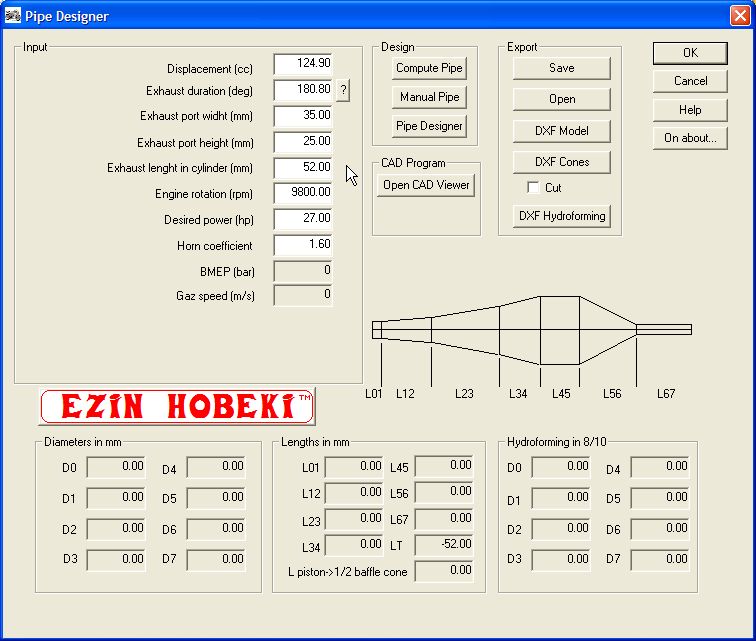
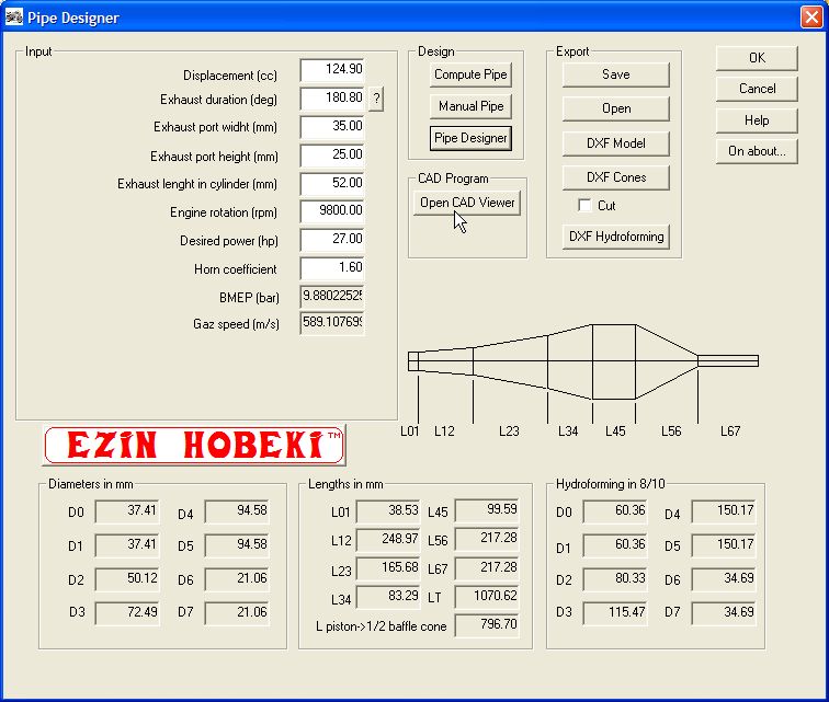
Here
is the opening form of Pipe Designer 1.2 full version program. |
| |
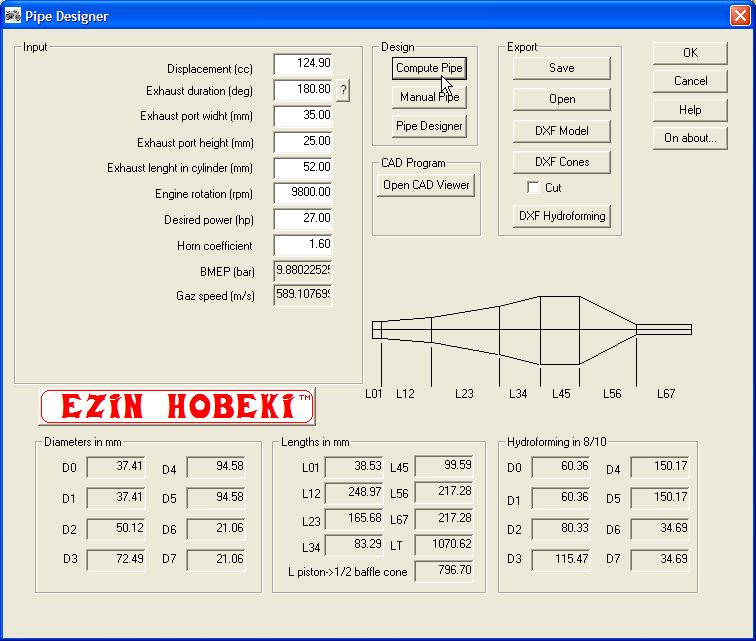
Clic on "Compute Pipe" to compute the dimension of your pipe according to your engine specification. The results appeares in the edit boxes below. |
| |
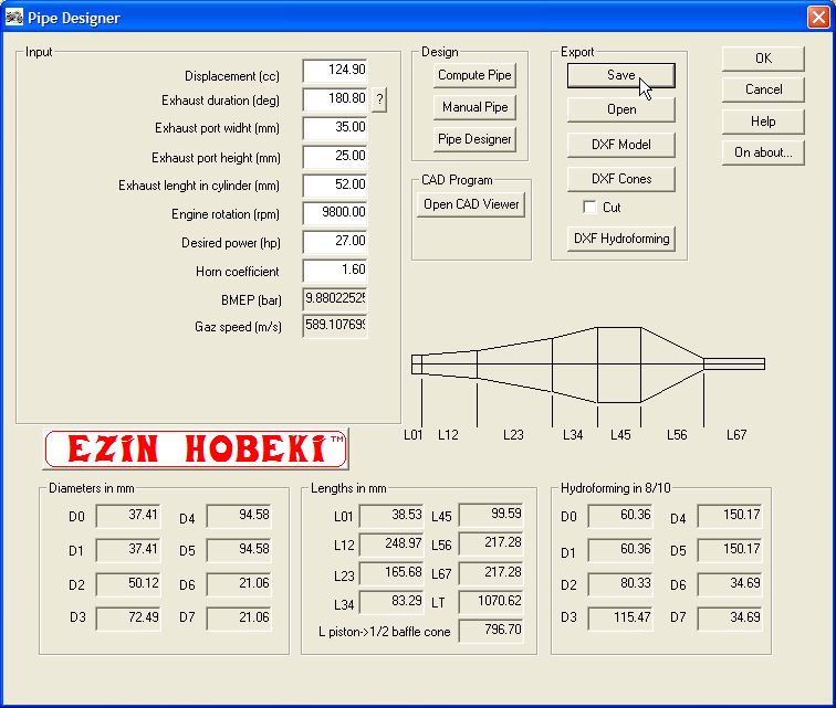
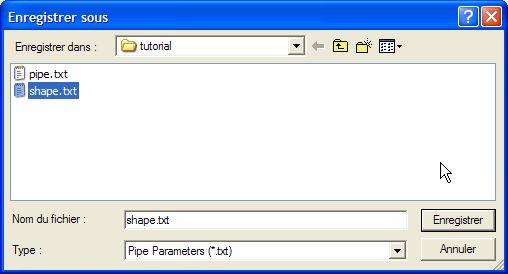
Clic on "Save" to save your parameters and computed data to a text file. |
| |
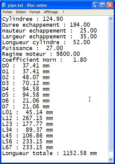
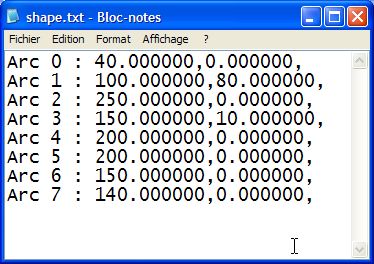
Here is a sample of saved data to the text file. |
| |
Clic on "Pipe Designer " in order to setup the neutral fiber of your pipe. |
| |
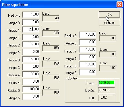
The 2D path
is computed using 8 different subpath from 0 to 7. Each subpath is
setup using 2 parameters : "Radius" and "Angle" (angle !!). If
the angle is set to 0 then the subpath is considered as a line. The
experimental length edit box should turn to green when the experimental
length is above 97% of theoretical length. The "L exp" Edit box turns to GREEN and then clic OK. Tip : Set the subpath 7 to L67 value from main form and then adjust the orthers. |
| |
Your parameters are saved in a text file. |
| |
Here is a sample of 2D pipe shape. |
| |
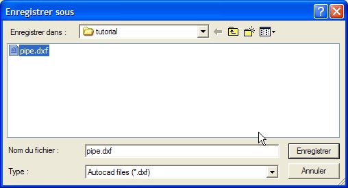
The 2D pipe template is
saved in a DXF file. On main form, clic on "Ouvre CAD Viewer" to chose your DXF view and open it to view the result. |
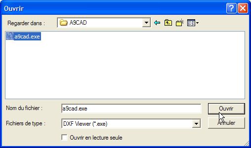
| Clic "Open CAD Viewer" to configure the path to the CAD program in our case A9CAD from A9Tech. |
| Browse your hard disk to find the CAD Viewer exe file and clic "Open" |
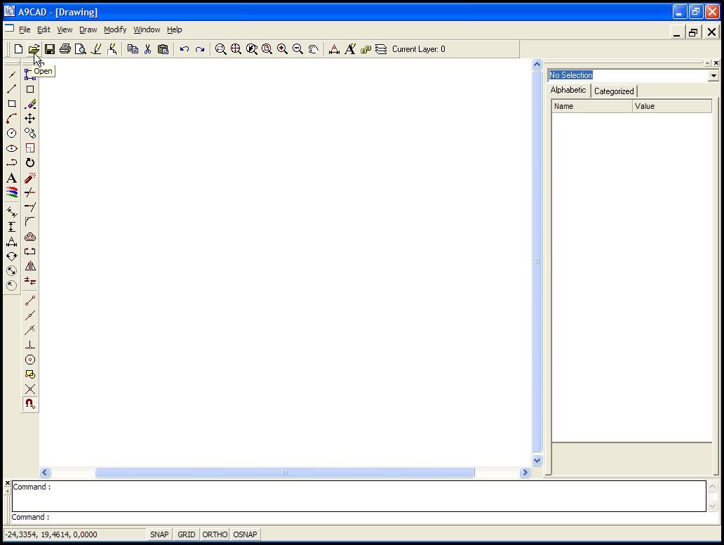
| When you CAD software is opened, select "Open" file icon or menu |
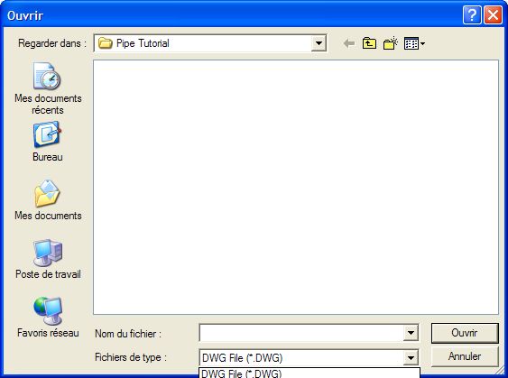
| Select de DXF format not the DWG one. |
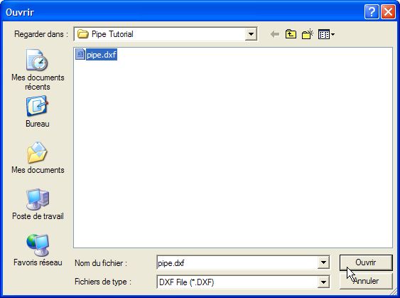
| Chose the file to be opened. |
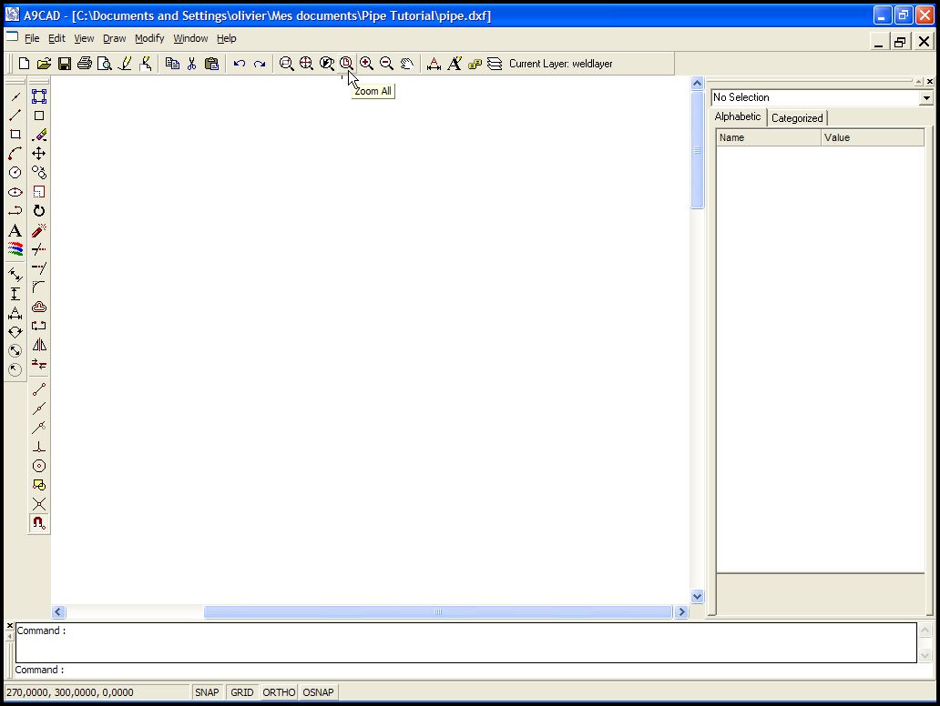
| File is opened but drawing not visible so select Zoom All icon to automatically center the drawing in the client rectangle of the window. |
| |
Here is a view of DXF file in A9CAD software. |
| |
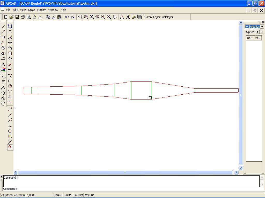
Clic on "DXF Model" to save the straight pipe in a DXF file |
| |
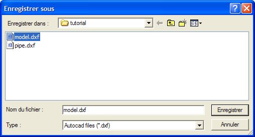
Chose your file name in the save as window. |
| |
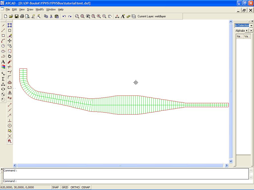
Here is a view of the pipe model DXF file in A9CAD software. |
| |
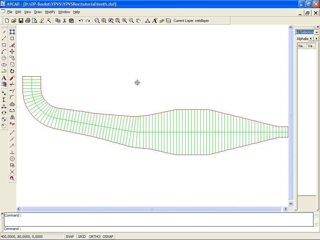
Clic "DXF Hydroformage" to compute and save the template for hydroforming of the pipe in a DXF file. |
| |
Here is a sample of Hydroforming DXF |