Due to a little bug pointed by an user, I’ve updated the software and we are now at 1.5.0 version.
Category Archives: Pipe Designer
Recent PipeDesigner users
Since January 2021 (last update), some new users
- Martin F. from Canada
- Mainer K. from Germany
- Frank L. from France
- Beate V. from Norway
- Ivo I. from Estonia
- Thomas A. from Suede
- Jochen L. at Asia Tech from Germany
- David M. from France
- Lionel S. from France
- Wayne N. from South Africa
Thanks to them for supporting my software development.
Recent PipeDesigner users
Since August 2020 (last update), some new users
- Ricardo C. from USA
- Frank S. from Germany
- Mark L. from Australia
Thanks to them for supporting my software development.
2020-07 PipeDesigner users
- In Austria
- Simon F.
Thanks to him
Tutorial for the new PipeDesigner version
A computation bug has been corrected and now, the new version allows the imagination of pipes…
On this exemple, we use the formula from Mr Blair.
Below, some screen shots of the steps :
- Pipe Designer => the button
- Hydroforming
- Button DXF Hydroforming
- Button DXF Hydroforming + check case “Cut”
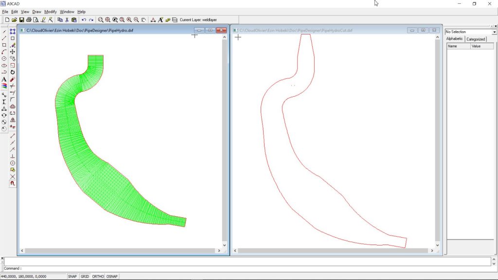
- Visualisation in A9CAD
Skeleton creation steps
- Image 1 : default values for the nine sections
- Image 2 : values for the skeleton
- Image 3 : saving the skeleton parameters in a texte file
- Images 4, 5 et 6 : DXF files creation
- Pipe
- Hydroforming flat pattern
- Hydroforming flat pattern for cutting
Results for the skeleton
DXF Visualisation
The pipe
Hydroforming patterns
2020-05 PipeDesigner users
- In France
- David D.
- Patrick F.
- In United Kingdom
- Simon L.
Thanks to them
2020-04 PipeDesigner users
- In Australia
- Trevor M.
- In Italia
- Gustavo M.
Thanks to them
2020 PipeDesigner users
- In France
- Thierry L. 15/01/2020
- Alain L. 15/02/2020
- In Belgium
- Florent L. 16/02/2020
Thanks to them.
Programs update
A little upgrade of the programs to improve their efficiency.
No major evolution but a better execution and installation.
New version of PipeDesigner
The new PipeDesigner program (2014-02-26) has been released with a export feature to ConeDesigner.
See the tutorial below for detail on getting the data for ConeDesigner.
Example: input data (by default in the GUI) :
Displacement : 124.90cc
Exhaust duration : 193.00°
Exhaust port height : 25.00mm
Exhaust port width : 35.00mm
Cylinder length : 52.00mm
Desired Power: 27.00HP
Engine Rotation : 9800.00 rpm
Coefficient Horn : 1.60
Step 1 => Click on “Compute Pipe” button => Result below
– Blair formulas
– Metal thickness 0.8mm (by default)
D0 : 37.41 mm
D1 : 37.41 mm
D2 : 50.12 mm
D3 : 72.49 mm
D4 : 94.58 mm
D5 : 94.58 mm
D6 : 21.06 mm
D7 : 21.06 mm
L01 : 44.64 mm
L12 : 265.77 mm
L23 : 176.86 mm
L34 : 88.91 mm
L45 : 106.31 mm
L56 : 231.94 mm
L67 : 231.94 mm
Total length : 1146.37 mm
Step 2 => Click the “Pipe Designer” button
– Put these data for the pipe profile for the 8 sections
Arc X : Rayon,Angle
Arc 0 : 44.640000,0.000000
Arc 1 : 253.800000,60.000000
Arc 2 : 176.000000,0.000000
Arc 3 : 88.910000,0.000000
Arc 4 : 36.310000,0.000000
Arc 5 : 35.000000,0.000000
Arc 6 : 35.000000,0.000000
Arc 7 : 950.000000,14.000000
Arc 8 : 950.000000,14.000000
– The following files will be created automatically :
– txt file for the parameters => PipeDesginer.txt
– DXF file for the pipe profile => PipeProfile.dxf
Step 3 => Open the file PipeDesginer.txt and he should contain the following data
You could verify that the diameters in this sample are exactly the same as the ones at step 1 because I pay attention to lengths of the 8 sections of the pipe shape (the cylindrical section has been split in 3 parts!!!)
Arc X : Rayon,Angle,DIn,Dout
Arc 0 : 44.640000,0.000000,37.409979,37.409979
Arc 1 : 253.800000,60.000000,37.409979,50.120635
Arc 2 : 176.000000,0.000000,50.120635,72.383361
Arc 3 : 88.910000,0.000000,72.383361,94.372427
Arc 4 : 36.310000,0.000000,94.372427,94.584018
Arc 5 : 35.000000,0.000000,94.584018,94.584018
Arc 6 : 35.000000,0.000000,94.584018,94.584018
Arc 7 : 950.000000,14.000000,94.584018,21.063705
Arc 8 : 950.000000,14.000000,21.063705,21.063705
DIn = Input diameter of the cone
DOut = Output diameter of the cone
Step 4 => Run ConeDesigner to create the unfold pattern of section Arc1
D2 = DOut = 50.120635mm
D1 = DIn = 37.409979mm
Angle A = Angle =60°
Radius R = Rayon = 253.80mm