I’m using the lock-down situation to update several projects…
I’ve made several electronic board to convert CDI signal to logical signal to enable wiring with modern dashboards or data acquisition device (like HRC). It is possible to configure the input:
+5v
+12v
+-200v
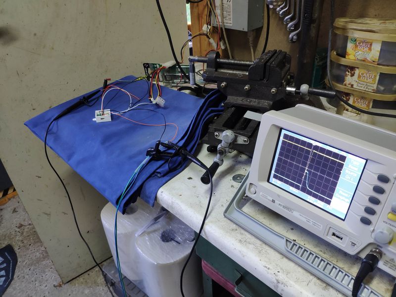
Board tested on a Yamaha TZR250 2XT
Several packages are available:
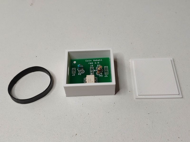
Simple board mounted and tested
Simple board mounted and tested + braided sleeving