The new PipeDesigner program (2014-02-26) has been released with a export feature to ConeDesigner.
See the tutorial below for detail on getting the data for ConeDesigner.
Example: input data (by default in the GUI) :
Displacement : 124.90cc
Exhaust duration : 193.00°
Exhaust port height : 25.00mm
Exhaust port width : 35.00mm
Cylinder length : 52.00mm
Desired Power: 27.00HP
Engine Rotation : 9800.00 rpm
Coefficient Horn : 1.60
Step 1 => Click on “Compute Pipe” button => Result below
– Blair formulas
– Metal thickness 0.8mm (by default)
D0 : 37.41 mm
D1 : 37.41 mm
D2 : 50.12 mm
D3 : 72.49 mm
D4 : 94.58 mm
D5 : 94.58 mm
D6 : 21.06 mm
D7 : 21.06 mm
L01 : 44.64 mm
L12 : 265.77 mm
L23 : 176.86 mm
L34 : 88.91 mm
L45 : 106.31 mm
L56 : 231.94 mm
L67 : 231.94 mm
Total length : 1146.37 mm
Step 2 => Click the “Pipe Designer” button
– Put these data for the pipe profile for the 8 sections
Arc X : Rayon,Angle
Arc 0 : 44.640000,0.000000
Arc 1 : 253.800000,60.000000
Arc 2 : 176.000000,0.000000
Arc 3 : 88.910000,0.000000
Arc 4 : 36.310000,0.000000
Arc 5 : 35.000000,0.000000
Arc 6 : 35.000000,0.000000
Arc 7 : 950.000000,14.000000
Arc 8 : 950.000000,14.000000
– The following files will be created automatically :
– txt file for the parameters => PipeDesginer.txt
– DXF file for the pipe profile => PipeProfile.dxf
Step 3 => Open the file PipeDesginer.txt and he should contain the following data
You could verify that the diameters in this sample are exactly the same as the ones at step 1 because I pay attention to lengths of the 8 sections of the pipe shape (the cylindrical section has been split in 3 parts!!!)
Arc X : Rayon,Angle,DIn,Dout
Arc 0 : 44.640000,0.000000,37.409979,37.409979
Arc 1 : 253.800000,60.000000,37.409979,50.120635
Arc 2 : 176.000000,0.000000,50.120635,72.383361
Arc 3 : 88.910000,0.000000,72.383361,94.372427
Arc 4 : 36.310000,0.000000,94.372427,94.584018
Arc 5 : 35.000000,0.000000,94.584018,94.584018
Arc 6 : 35.000000,0.000000,94.584018,94.584018
Arc 7 : 950.000000,14.000000,94.584018,21.063705
Arc 8 : 950.000000,14.000000,21.063705,21.063705
DIn = Input diameter of the cone
DOut = Output diameter of the cone
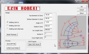
Step 4 => Run ConeDesigner to create the unfold pattern of section Arc1
D2 = DOut = 50.120635mm
D1 = DIn = 37.409979mm
Angle A = Angle =60°
Radius R = Rayon = 253.80mm


